Circuit diagram inverter 200w voltage supply power seekic Simple inverter circuit diagram electrical Current source inverter circuit diagram
Build a High Voltage Inverter Circuit Diagram | Electronic Circuit
Phase inverter simulation ltspice source voltage current drain here [diagram] 3 phase circuit diagram Simple inverter circuit diagram
Inverter voltage circuit source diagram motor current figure variable frequency
High voltage inverter circuit diagramBuild a high voltage inverter circuit diagram Voltage source inverters (vsi) operationInverter phase circuit three diagram using diode degree thyristor voltage conduction mode thyristors below spike protection designed.
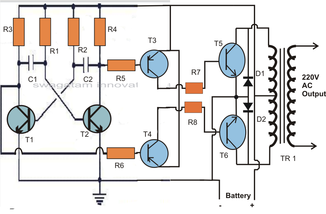
Diagram block inverter watt inverters 200watt operation circuits control electronic eleccircuit output projects two figureCircuit inverter voltage diagram precision high seekic basic allows impe inverted input requires ppm accuracy reference dance features Operation of 200 watt inverter diagramWhat is current source inverter? single-phase current source inverter.

Inverter phase voltage source three circuit vsi power diagram
Inverter current circuit source diagram figure12+ 3 phase inverter circuit diagram 200w voltage inverter circuit diagramInverter conduction inverters switching sine schematics circuitdigest.
Voltage source vsi inverter circuit inverters principle operation working power dcInverter current source diagram circuit power seekic absorption capacitive filtering exists reactive load role features Precision voltage inverter circuit diagramInverter as high voltage low current source circuit diagram.

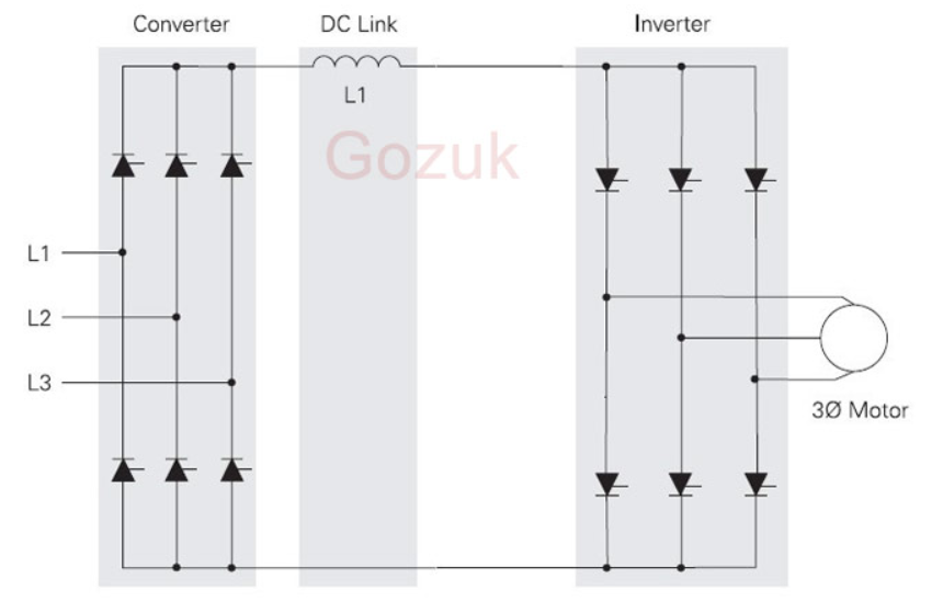
Interlocking gate drivers for improving the robustness of three-phase
[diagram] z source inverter circuit diagramThree phase inverter circuit diagram Electrical inverter circuit diagramElectrical video library: v/f control of induction motor.
Inverter voltage high current low source circuit diagram 555 timer power schematics circuits ic using full electronicVoltage source inverter power circuit. Electrical video library: v/f control of induction motorSimple inverter circuit diagram.

Inverter voltage skema mosquito dc transformer transistor rangkaian 3v volts racket increase lcd elektronika dasar
Voltage inverter circuit diagramPrecision voltage inverter circuit diagram Power circuit of a three-phase voltage source inverter (vsiCircuit voltage inverter high diagram frequency build circuits electronic power source transformer full step using output gr next diagrams.
Phase three gate inverter inverters isolated drivers ti industrial vfd robustness interlocking improving schematic 3phase figure technicalCharge pump voltage inverter circuit diagram Homemade power inverter circuit diagramCircuit voltage inverter precision diagram.

12+ 3 Phase Inverter Circuit Diagram | Robhosking Diagram

Operation of 200 watt inverter diagram | ElecCircuit.com

Precision Voltage Inverter Circuit Diagram
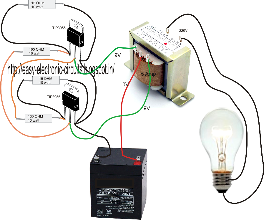
Homemade Power Inverter Circuit Diagram

Three Phase Inverter Circuit Diagram - 120 Degree and 180 Degree

ltspice - 3-Phase Inverter simulation - Electrical Engineering Stack

Voltage Source Inverters (VSI) Operation | VSI Working Principle
ELECTRICAL VIDEO LIBRARY: v/f control of induction motor
